Our company constantly improves the production process, accurately controls the product manufacturing process, and produces multi specification and high-quality PCB Assembly Services, SMT&DIP PCB Assebly One Stop EMS Service, Smarthome Smt Dip Pcba. We hope to continue to promote industry reform and innovation, drive the industry and complete sets of equipment to overseas, and form a wide and far-reaching influence. We develop and provide goods and services useful to society and contribute to the sustainable development of society
Vibration Sensor Controller PCBA for LED Lights:
Design, Specifications & Applications
1. Product Overview
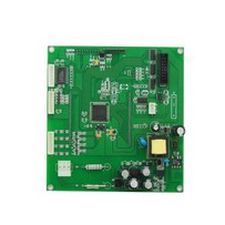
The Vibration Sensor Controller PCBA integrates a high-precision vibration sensing module, a dedicated control circuit, and an LED light driving system into a single printed circuit board assembly. It is designed to realize vibration-triggered LED lighting functions-automatically activating, dimming, or switching LED lights based on detected vibration signals (e.g., intensity, frequency, duration). This product combines the sensitivity of vibration detection with the energy efficiency of LED lighting, making it ideal for scenarios requiring responsive, low-power lighting solutions, such as industrial equipment status indication, smart home security alerts, and automotive auxiliary lighting.
Unlike traditional LED controllers that rely on manual switches or fixed timers, this PCBA uses real-time vibration data to adjust LED behavior, enhancing usability, energy savings, and safety. For example, in industrial settings, it can trigger bright LED warnings when abnormal vibration (indicating equipment malfunction) is detected; in smart homes, it can activate soft LED pathway lights when vibration from door opening/closing is sensed.
2. Core Specifications
2.1 Vibration Sensor Module Specifications
| Parameter | Details |
|---|---|
| Sensor Type | MEMS (Micro-Electro-Mechanical Systems) vibration sensor (preferred for small size, high sensitivity) or piezoelectric vibration sensor (for high-frequency vibration detection) |
| Detection Range | Vibration acceleration: 0.1g - 20g (adjustable via PCBA firmware); Frequency range: 1Hz - 5000Hz (covers most industrial, automotive, and home vibration scenarios) |
| Sensitivity | ≤ 0.01g (minimum detectable vibration), ensuring accurate response to weak signals (e.g., light door vibration) |
| Output Signal | Digital signal (ON/OFF trigger) or analog signal (vibration intensity proportional voltage, 0-3.3V/0-5V) |
| Power Consumption | ≤ 5mA (standby mode), ≤ 15mA (detection mode) – low power for battery-powered applications |
2.2 LED Driving & Control Specifications
| Parameter | Details |
|---|---|
| LED Compatibility | Supports single-color (red, green, blue, white) or RGB LED arrays; LED current range: 10mA - 500mA (adjustable via current-limiting resistors or PWM) |
| LED Control Modes | Vibration-triggered modes:- On/Off: LED turns on when vibration is detected, turns off after a set delay (5s - 600s, configurable)- Dimming: LED brightness adjusts with vibration intensity (e.g., 30% brightness for weak vibration, 100% for strong vibration)- Strobing: LED flashes (1Hz - 10Hz) for abnormal vibration (e.g., equipment overload) |
| PWM Dimming Resolution | 8-bit - 12-bit (256 - 4096 brightness levels), ensuring smooth brightness transitions |
| Voltage Input | DC 5V - 24V (wide range for industrial power supplies, automotive 12V systems, or home 5V USB power) |
| Power Efficiency | ≥ 85% (LED driving circuit), minimizing energy loss and heat generation |
2.3 PCB & Assembly Specifications
| Parameter | Details |
|---|---|
| PCB Type | Rigid PCB (standard) or rigid-flex PCB (for curved/space-constrained installations, e.g., automotive interiors) |
| Substrate Material | FR4 (Tg ≥ 150°C, for general use) or high-temperature FR4 (Tg ≥ 170°C, for industrial/automotive high-heat environments) |
| Layer Count | 2-layer (cost-effective for simple circuits) or 4-layer (for complex designs with separate power/ground layers to reduce noise) |
| Component Placement | SMT (Surface Mount Technology) for miniaturization:- Vibration sensor: 0805/0603 package (small size, easy integration)- MCU (control chip): QFP32/LQFP48 package (e.g., STM32F0 series, low power, rich I/O)- LED driver IC: SOT23-6/SOP8 package (e.g., TI TPS61040, high-efficiency step-up converter) |
| Surface Finish | ENIG (Electroless Nickel Immersion Gold) – corrosion-resistant, suitable for long-term use; OSP (Organic Solderability Preservative) – cost-effective for low-volume orders |
| Environmental Tolerance | Operating temperature: -40°C to 85°C (wide range for outdoor/industrial use); Humidity: 10% - 90% RH (non-condensing) |
3. Working Principle
The Vibration Sensor Controller PCBA operates in three core stages, enabling seamless coordination between vibration detection and LED control
3.1 Vibration Signal Detection
The Vibration Sensor Controller Pcba Led Lights vibration sensor converts mechanical vibration into an electrical signal (analog voltage or digital pulse).
The signal is amplified and filtered by the PCBA's analog front-end circuit (e.g., op-amp LM358) to eliminate noise (e.g., ambient micro-vibrations).
The filtered signal is sent to the MCU (main control unit), which processes the data to determine vibration parameters:
Presence of vibration: Whether the signal exceeds the preset threshold (e.g., 0.1g) to avoid false triggers.
Vibration intensity: For analog sensors, the MCU converts the voltage signal to acceleration values (via ADC, 12-bit resolution).
Vibration frequency: The MCU counts signal pulses to identify frequency (e.g., 50Hz for industrial motor vibration, 1Hz for door vibration).
3.2 LED Control Logic Execution
Based on the processed vibration data, the MCU executes pre-programmed control logic (configurable via firmware):
Basic Trigger: If vibration intensity > threshold (e.g., 0.5g), the MCU sends a signal to the LED driver IC to turn on the LED; after the delay timer expires (e.g., 30s), the LED turns off.
Intensity Adjustment: For analog vibration signals, the MCU calculates brightness percentage (e.g., 0.1g → 30% brightness, 5g → 100% brightness) and outputs a PWM signal to the LED driver, which adjusts the LED current accordingly.
Abnormal Alert: If vibration frequency exceeds the safe range (e.g., > 1000Hz for industrial equipment), the MCU triggers LED strobing (5Hz) and can send an alert signal via optional communication ports (e.g., UART, IoT modules like ESP8266).
3.3 Energy Management
To optimize power efficiency, the PCBA includes two energy-saving mechanisms:
Standby Mode: When no vibration is detected for > 5 minutes, the MCU enters low-power mode (current ≤ 5mA), shutting down non-essential circuits (e.g., analog front-end) while keeping the sensor in "watchdog" mode.
PWM Dimming: Instead of using resistors to reduce LED brightness (which wastes energy), the MCU uses PWM to cycle the LED on/off rapidly (≥ 100Hz, imperceptible to the human eye), cutting power consumption by up to 70% at low brightness levels.
4. Key Applications
The Vibration Sensor Controller Pcba Led Lights PCBA for LED Lights is versatile, with applications across industrial, automotive, smart home, and commercial sectors:
4.1 Industrial Equipment Monitoring
Use Case: Status indication for motors, pumps, or conveyors.
Function: When equipment vibration exceeds the normal range (e.g., 5g for a motor), the PCBA triggers red LED strobing to alert maintenance staff; normal vibration (≤ 1g) keeps a green LED on.
Advantage: Reduces manual inspection frequency, enabling proactive equipment maintenance and minimizing downtime.
4.2 Automotive Auxiliary Lighting
Use Case: Trunk/door LED lights, undercarriage warning lights.
Function: When the car door is opened (vibration from door hinge), the PCBA activates white LED trunk lights; when the vehicle is in motion (vibration from the engine), it turns off unnecessary LEDs to save battery. For off-road vehicles, strong vibration (e.g., from rough terrain) triggers yellow LED undercarriage lights to illuminate obstacles.
Advantage: Eliminates the need for door switches, reducing wiring complexity; adapts to driving conditions for energy savings.
4.3 Smart Home Security & Convenience
Use Case: Pathway lights, cabinet lights, security alerts.
Function: Vibration from opening a bedroom door triggers soft white LED pathway lights (turns off after 60s); vibration from a window being forced open (abnormal high intensity, > 2g) triggers red LED flashing and connects to a smart speaker (via Wi-Fi module) to sound an alert.
Advantage: No manual switches, enhancing convenience; provides passive security monitoring.
4.4 Commercial & Public Spaces
Use Case: Staircase lights, vending machine status lights.
Function: Vibration from footsteps on stairs triggers LED staircase lights (brightness adjusts with footstep frequency); vibration from vending machine coin insertion turns on a green LED to confirm payment, while abnormal vibration (e.g., tampering) triggers orange LED strobing.
Advantage: Saves energy compared to always-on lights; provides real-time user feedback.
5. Quality Assurance & Compliance
To ensure reliability and safety, the Vibration Sensor Controller PCBA undergoes strict quality control and complies with international standards:
5.1 Testing Procedures
| Test Type | Details |
|---|---|
| Vibration Sensor Calibration | Each PCBA is tested with a vibration shaker (frequency 1Hz - 5000Hz, acceleration 0.1g - 20g) to verify sensor accuracy; calibration data is stored in the MCU for firmware adjustment. |
| LED Function Testing | Tests all LED control modes (on/off, dimming, strobing) with different vibration inputs; verifies brightness consistency (±5%) and response time (< 100ms). |
| Environmental Testing | - Temperature Cycling: -40°C to 85°C, 100 cycles (1 hour/cycle) – ensures stable operation in extreme temperatures.- Vibration Resistance: 10Hz - 2000Hz, 10G acceleration, X/Y/Z axes (2 hours/axis) – simulates long-term use in vibrating environments (e.g., automotive, industrial).- Humidity Testing: 40°C, 90% RH, 500 hours – prevents moisture-induced circuit failure. |
| Electrical Safety Testing | - Insulation resistance: ≥ 100MΩ (500V DC) – avoids electric shock.- Overvoltage testing: 120% of rated input voltage (e.g., 28.8V for 24V input) for 1 hour – ensures circuit protection against voltage spikes. |
5.2 Certifications
Electrical Safety: UL 60950-1 (for IT/AV equipment), IEC 61558-1 (for power supplies).
EMC (Electromagnetic Compatibility): CE (EN 55032 Class B, for low electromagnetic radiation), FCC Part 15B (US EMC standard).
Environmental Compliance: RoHS 2.0 (restricts lead, cadmium, mercury, etc.), REACH (no SVHC substances exceeding 0.1%).
6. F&A (Frequently Asked Questions & Answers)
6.1 Can the vibration trigger threshold of the PCBA be adjusted according to my application needs?
Yes, the vibration trigger threshold is fully adjustable to match different application scenarios. For analog vibration sensors, the threshold (e.g., 0.1g for home door vibration, 5g for industrial motor vibration) can be modified via firmware programming-we can pre-set the threshold based on your requirements before delivery, or provide a simple configuration tool (e.g., a USB-based software interface) for you to adjust it on-site. For digital vibration sensors, the threshold is set via external resistors, which we can customize during PCB design to avoid post-installation modifications.
6.2 Is the PCBA compatible with high-power LED arrays (e.g., 10W or above)?
Absolutely. The standard PCBA supports LED currents up to 500mA, which is suitable for low-to-medium power LEDs (e.g., 1-5W). For high-power LED arrays (10W or above, requiring currents > 500mA), we can upgrade the LED driving circuit by integrating high-current driver ICs (e.g., TI TPS92691, supporting up to 3A current) and adding heat sinks to the PCB (e.g., aluminum-based PCB or attached thermal pads). This modification ensures stable driving of high-power LEDs without overheating, while maintaining the same vibration-triggered control logic.
6.3 How to avoid false triggers caused by ambient micro-vibrations (e.g., wind blowing, small impacts)?
We have three built-in anti-false-trigger mechanisms to solve this problem:
Threshold Filtering: The MCU ignores vibration signals below the preset threshold (e.g., 0.05g), which can be set to be higher than the intensity of ambient micro-vibrations.
Duration Verification: The PCBA only triggers LED actions if the vibration signal lasts for a minimum duration (e.g., 100ms) – short micro-vibrations (e.g., 20ms from wind) are automatically filtered out.
Frequency Recognition: For scenarios with fixed ambient vibration frequencies (e.g., 50Hz from nearby motors), the MCU can be programmed to exclude signals of that specific frequency, ensuring only target vibrations (e.g., 1Hz from door opening) trigger the LED
6.4 What is the service life of the PCBA, and is there a warranty period?
The expected service of Vibration Sensor Controller Pcba Led Lights life of the PCBA is 5-8 years under normal operating conditions (within the specified temperature, humidity, and vibration ranges). This is ensured by using long-life components: MEMS vibration sensors (service life ≥ 10 years), high-quality MCUs (operating life ≥ 8 years), and LED driver ICs (MTBF ≥ 50,000 hours). We provide a 2-year warranty for all standard PCBA products – during the warranty period, we offer free repair or replacement for any defects caused by material or manufacturing issues. For industrial/automotive applications requiring longer durability, we can extend the warranty to 3 years by using automotive-grade components (e.g., AEC-Q100 certified MCUs).
7. Quote & Customization Requirements
To provide a tailored quote and customize the Vibration Sensor Controller PCBA for your specific needs, please provide the following information:
6.1 Basic Technical Requirements
Vibration detection range (acceleration/frequency) and trigger threshold (e.g., 0.3g for home use, 5g for industrial use).
LED specifications: Color (single/RGB), quantity, current (e.g., 200mA per LED), and control modes (on/off only or dimming/strobing).
Input voltage (e.g., 12V for automotive, 5V for USB-powered devices) and power consumption limits.
6.2 Design Files & Samples
Gerber files (RS-274X format) for PCB layout (if customizing the board size/shape).
BOM list (if specifying preferred components, e.g., a specific MEMS sensor model like ADXL345).
Reference sample (if available) of the desired LED lighting behavior (e.g., a video of vibration-triggered dimming).
6.3 Application-Specific Needs
Operating environment (e.g., outdoor, high-temperature industrial area) to confirm environmental tolerance.
Additional functions (e.g., Wi-Fi/Bluetooth connectivity for smart control, battery backup for power outages).
Production volume (e.g., 100 units for prototyping, 10,000 units for mass production) to optimize pricing.
Normally customer-oriented, and it's our ultimate concentrate on for 37 in 1 Electronic Sensor Module Starter Kit for Uno R3, 37 Sensor Kit. We strengthen the construction of our workforce with quality improvement and ability cultivation as the core. We strengthen the alliance, collaboration, reinvestment and joint development overseas.
Hot Tags: vibration sensor controller pcba led lights, China, manufacturers, factory, customized, productivity enhancement of pcb assembly, Turnkey PCBA Assembly Service, ONE STOP SERVICE, custom components sourcing, pcb assembly with anti static packaging, Led Round Printed Circuit Board Pcba Pcb Assembly
[[ProKeywords]]