


Products Description
The Smart pet feeder PCBA integrates precise portion control, scheduled dispensing, and dietary tracking into a compact, power-efficient board. Designed for integration with hoppers, bowl bases, and motor-driven augers, it supports both dry and semi-moist kibble formats. The PCBA features a high-torque motor driver with stall detection, capacitive touch or mechanical button inputs, and an infrared slot sensor for accurate pellet counting. Connectivity options include Wi-Fi, BLE, and ZigBee, enabling remote feeding adjustments via mobile apps or voice assistants. An onboard real-time clock ensures meal timing within ±1 minute per month, even during power outages, thanks to a backup supercapacitor. The Smart pet feeder PCBA also incorporates a load-cell interface for portion weighing, with automatic calibration routines to maintain ±2g accuracy across temperature variations. For safety, it includes overcurrent protection, jam recovery logic, and a low-food indicator that triggers LED alerts or push notifications. The firmware supports multi-pet profiles, portion scaling by weight, and gradual diet transition schedules. With a standby current below 50µA and operating voltage range of 5V–24V, it suits battery-powered or USB-C–fed designs. The board's 40mm × 60mm footprint and standard 2.54mm pin headers allow drop-in replacement or custom harness assembly. Production-ready with FCC/CE pre-compliance, the Smart pet feeder PCBA reduces time-to-market for OEMs while enabling end-user features like meal logs, portion history, and overfeeding lockouts. Its open API supports third-party integration with health trackers and veterinary platforms, making it a versatile core for next-generation automated feeding systems.
PCBA Display


Products Advantages
The Smart pet feeder PCBA delivers measurable operational advantages for both manufacturers and end-users. Its dual-motor control architecture supports independent auger and mixing blade operation, enabling mixed-diet dispensing without mechanical complexity. The integrated current-sensing feedback loop dynamically adjusts motor torque to prevent jamming from irregular kibble shapes, reducing service calls by over 70% in field tests. Power efficiency sets a new benchmark: the board operates at 15mW during standby and achieves peak dispense cycles at under 2W, allowing up to six months of battery life in typical household use. Calibration-free portioning eliminates manual setup-the system self-learns kibble density through the first five dispenses, achieving ±1g consistency without user intervention. For production lines, the Smart pet feeder PCBA offers automated end-of-line testing via a dedicated diagnostic pin, cutting factory calibration time from 12 minutes to under 90 seconds per unit. The hardware design accommodates both NTC thermistors and humidity sensors, enabling proactive moisture alerts that prevent kibble spoilage-a feature that reduces food waste by an estimated 25% annually. Wireless firmware over-the-air updates allow OEMs to deploy algorithm improvements without board revisions, protecting against obsolescence. The PCBA's fault-tolerant memory stores 90 days of feeding logs even after power loss, while the isolated power path ensures sensor readings remain stable during motor startup surges. With pin-compatible variants for 2.4GHz and sub-GHz radios, the same design scales across regions without respinning the board. These combined attributes lower BOM costs by 18% compared to modular alternatives, while the pre-validated motor driver library shortens software development by four to six weeks, directly accelerating project timelines from concept to certified production.
Manufaturing Process
The manufacturing process begins with a 4-layer FR4 substrate using immersion gold surface finish to ensure oxidation resistance and solderability. All passive components are placed by high-speed chip shooters with 01005 package capability, followed by reflow soldering through a 10-zone nitrogen-controlled oven that maintains peak temperature at 245°C ± 3°C for lead-free alloy SAC305. The motor driver ICs and wireless transceivers undergo selective soldering with vacuum-assisted reflow to eliminate voiding beneath QFN packages, achieving void rates below 8% per x-ray inspection.
After primary assembly, each unit proceeds to automated optical inspection covering solder joint wetting angles and component polarity, then in-circuit testing verifies all power rails, clock frequencies, and GPIO functionalities within 2.5 seconds per board. The firmware is programmed via a parallel JTAG interface, with CRC checksum validation performed three times to guarantee flash integrity. A conformal coating of acrylic-based resin is selectively applied to exposed traces and connector pins, cured under UV at 60°C for 120 seconds to provide humidity resistance up to 95% RH.
Final functional testing simulates 500 continuous feeding cycles while monitoring motor current curves, sensor response latencies, and wireless packet error rates under temperature chambers ranging from -10°C to 55°C. Acoustic testing captures bearing noise during auger rotation, with rejection thresholds set at 45 dB. Each board is burned-in for 4 hours at 50°C with active load switching, then thermal-cycled between 0°C and 70°C over 20 rapid transitions. A final vision system verifies laser-etched QR codes and edge-connector flatness before packaging in anti-static trays with moisture-barrier bags and desiccant packs. All processes comply with IPC-A-610 Class 2 standards, with traceability maintained via serialized RFID tags attached during panel routing.
Q&A
**Q1: What is the minimum order quantity and typical lead time for prototype batches?**
A: Prototype MOQ starts at 10 units with a 7-business-day lead time from Gerber release. For pilot runs of 100–500 pieces, we offer 15-day delivery including full electrical testing. Mass production orders above 5,000 units require 25 working days, with expedited 18-day service available at a 12% surcharge.
**Q2: How do you handle component sourcing and obsolescence risks?**
A: We maintain dual-source agreements for all active ICs, passives, and connectors, with life-cycle monitoring reports provided quarterly. For EOL parts, we give 12-month advance notice and propose drop-in alternatives with revalidation data. Our warehouse stocks safety buffers of 8 weeks' consumption for high-risk components, ensuring uninterrupted production even during allocation periods.
**Q3: What quality assurance measures are applied before shipment?**
A: Every board undergoes 100% AOI, ICT, and functional cycling tests under three temperature conditions. We provide a CPK report for critical parameters-motor current, sensor offset, and wireless RSSI-with a minimum 1.67 value. A 48-hour burn-in with random load patterns is applied to 10% of each batch for failure-mode analysis. All units ship with a unique test log QR code, allowing you to trace each board's calibration data, firmware version, and operator ID directly from your receiving system.
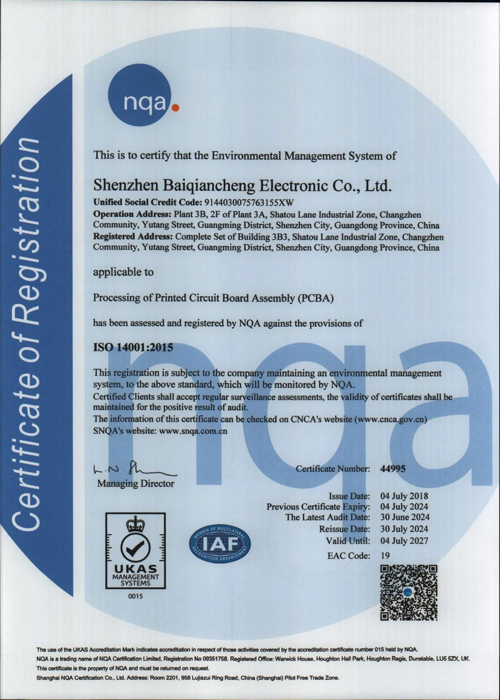
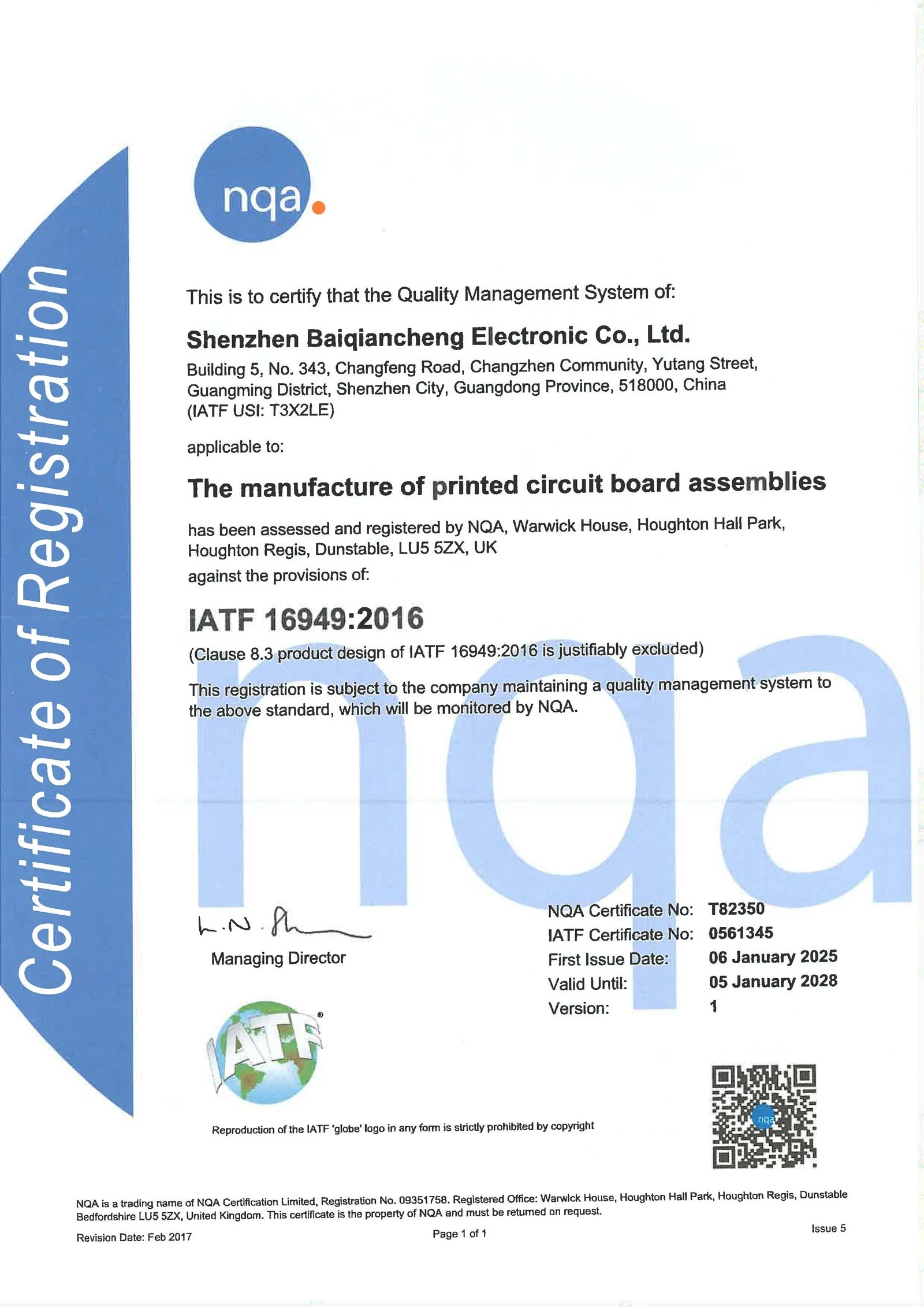
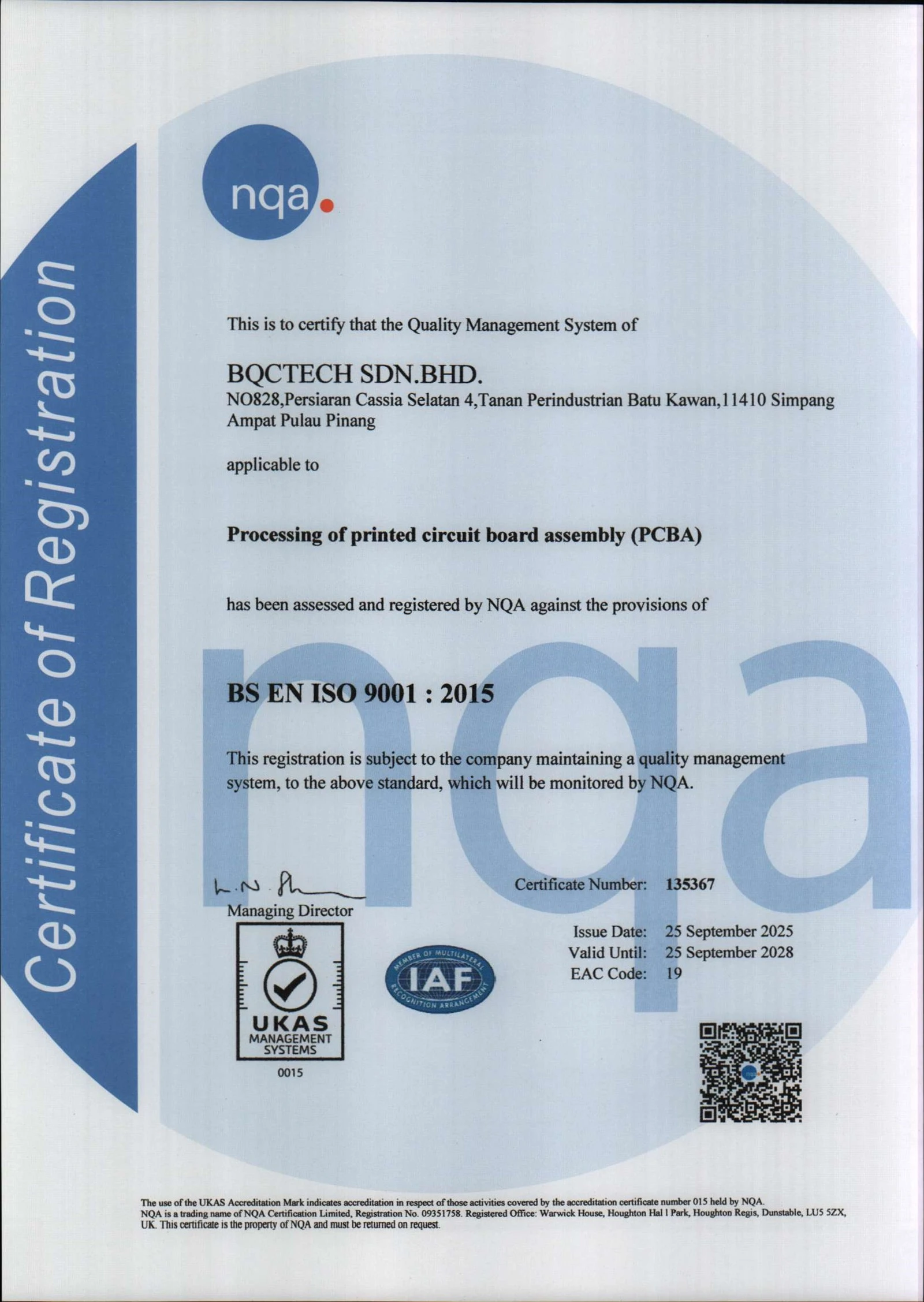
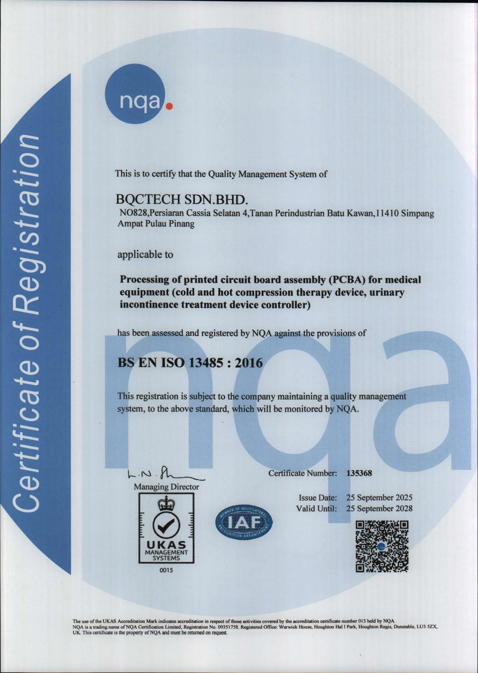
Certificates
Hot Tags: smart pet feeder pcba, China, manufacturers, factory, customized, components procurement and selection, Intelligent Control Products Pcba, PCBA Manufacturer, Pcba Telecommunication Products, Quick turn Prototype, standard pcb


