


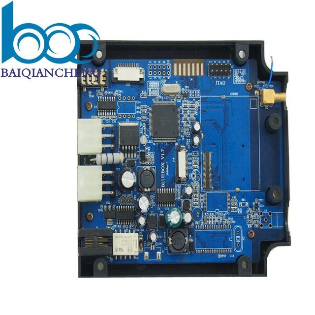
Products Description
The Servo Drive PCBA is engineered as the high‑performance power and control core for precise motion systems in industrial automation and robotics. It integrates a fast digital signal processor running advanced field‑oriented control algorithms, enabling smooth, accurate control of permanent magnet synchronous motors (PMSM) and brushless DC motors. The board features a three‑phase inverter stage using low‑loss IGBTs or SiC MOSFETs, with isolated gate drivers that provide high noise immunity and fast switching. Precision current sensing via isolated sigma‑delta modulators provides real‑time feedback for closed‑loop torque and velocity control. Multiple feedback interfaces support incremental encoders, absolute encoders (BiSS, EnDat), and resolvers. On‑board protection includes overcurrent, overvoltage, undervoltage, and overtemperature monitoring, with safe torque off (STO) inputs for functional safety. The PCB uses heavy copper planes for high‑current paths and a careful grounding scheme to isolate power and signal grounds. Communication interfaces include EtherCAT, CANopen, and Modbus for integration into industrial networks. The board is conformal‑coated and designed for extended temperature ranges, making it suitable for machine tools, packaging equipment, and collaborative robots.
PCBA Display


Production Process
The assembly of servo drive boards requires precise handling of high‑current power stages and sensitive feedback circuits. Solder paste printing uses Type 4 powder with SPI to ensure consistent volume on fine‑pitch pads of the DSP, FPGA, and isolated gate drivers, while larger stencil apertures accommodate high‑current inverter module pads. Reflow is performed with a multizone oven under nitrogen, using a profile that delivers sufficient thermal energy for heavy copper planes and power modules without damaging sensitive analog components. X‑ray inspection is mandatory for IGBT/SiC modules and current sense transformers to verify void levels and solder coverage. After reflow, selective soldering attaches thru‑hole bus bars, terminal blocks, and DC‑link capacitor pins. A robotic selective coating robot applies a thick conformal coating to protect against dust and condensation, with mask tooling protecting connector pins, test points, and heatsink mounting areas. Board depanelization uses routing with entry/backup material to prevent burrs. Final assembly includes installation of thermal pads or heatsinks on power modules, the rectifier bridge, and any required isolation barriers. Each board then undergoes a high‑potential test (hipot) to verify isolation integrity before powered functional testing. All assembly is performed in ESD‑safe workstations with controlled humidity, and high‑voltage sections are clearly identified during handling.
Production and Quality
Our production workflow for servo drive assemblies is built around strict process discipline and end‑to‑end traceability. Every unit moves through In‑Circuit Verification followed by a dynamic load‑based Functional Check. During this check, we evaluate current loop response, velocity regulation, position accuracy, and compatibility with multiple feedback types including incremental, absolute, and resolver interfaces. Fieldbus communication is exercised under live traffic for EtherCAT and CANopen. Fault handling is confirmed by deliberately injecting overcurrent and overvoltage events to ensure trip thresholds are correct. The STO path is validated with redundant triggers to confirm safe shutdown within the required time.
Production lines are equipped with 3D solder paste inspection, automated optical inspection, and X‑ray for power modules and gate drivers. A thick protective coating is applied to resist dust and moisture. Each assembly completes a 48‑hour elevated‑temperature burn‑in with continuous dynamic cycling to expose early life failures.
We hold long‑term supply agreements for DSPs, power modules, and isolated gate drivers. Volume orders ship in 8–10 weeks. High‑precision placement equipment and dedicated motor test stations give us the scalability to support industrial motion control build schedules while maintaining stable output and on‑time delivery.
Q&A
Q: What is the most critical test to ensure a servo drive will not oscillate or become unstable in the field?
A: The most critical test is current loop bandwidth and phase margin verification under realistic load conditions. A Servo Drive PCBA that passes basic functional tests can still oscillate when connected to a real motor with varying inertia. We use a motor emulator that simulates different inductance and resistance values. The FCT injects a small‑signal step into the current loop and measures the response. We calculate bandwidth and phase margin in real time. Any board with phase margin below 45 degrees or bandwidth outside the specified range is rejected. This catches layout‑induced noise or component tolerance issues that would cause audible hum or vibration in the field.
Q: How do you test the safe torque off (STO) function without risking injury or equipment damage?
Answer: We treat STO as a safety‑critical function and test it with redundant hardware. The FCT fixture applies power to the drive and commands the motor to rotate. It then activates STO through two independent channels. The test system verifies that within 10ms, the PWM outputs are disabled and the motor coasts to a stop. We also verify that a single fault (one channel stuck high) still results in a safe shutdown. The test is performed on every board, and the results are logged with a timestamp. No manual intervention is allowed during this test – the fixture automatically confirms the safe state before releasing the board.
Q: What measures ensure long‑term reliability of the DC‑link capacitors and power modules?
Answer: We perform accelerated power cycling on a statistical sample from each batch. The board is run at full load with a 5‑second on / 5‑second off cycle for 1,000 cycles. This simulates years of thermal expansion and contraction. After cycling, we measure the DC‑link capacitance and ESR, and we verify the power module's thermal resistance. Any degradation beyond 10% fails the batch. For 100% of production, we verify the DC‑link voltage ripple at full load; excessive ripple indicates a weak capacitor or poor solder joint. Additionally, we monitor the power module case temperature during burn‑in using an infrared sensor; any hot spot above the specified limit triggers a rework of the heatsink interface.
Certificates


Hot Tags: servo drive pcba, China, manufacturers, factory, customized, OEM Manufacturer, PCB Assembly Turnkey Service, pcb for industrial control, pcb layout, Quick turn Prototype, SMT Led Pcba


