


Products Description
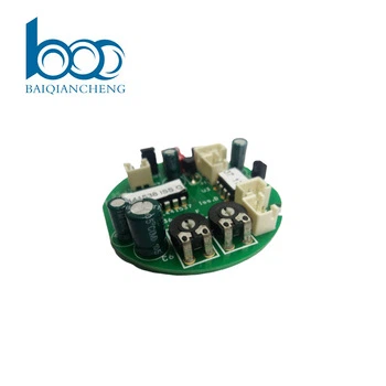
The Ventilation equipment PCBA is engineered as the intelligent control hub for modern air handling systems. It integrates a high‑performance microcontroller managing fan speed via PWM or VFD drivers, with real‑time feedback from pressure and airflow sensors to maintain setpoint air volume. On‑board temperature and humidity channels enable demand‑controlled ventilation, automatically adjusting fan operation to meet occupancy or comfort needs. The board includes isolated digital inputs for safety interlocks (fire alarms, filter status) and low‑leakage relay outputs for damper actuators. A precision analog input stage reads 0‑10V or 4‑20mA signals from external CO₂ or VOC sensors for IAQ optimization. Power management provides stable rails for internal logic and external peripherals, while robust EMC filtering handles installation near inverters and motors. The PCB layout uses guarded analog traces and separated power/control zones to ensure stable sensor readings even during high‑current motor switching. Designed for 24/7 continuous operation, the PCBA supports a wide range of supply voltages and industrial temperature ranges, with conformal coating and terminal‑block connectors for easy field wiring. It is suitable for AHUs, HRVs, ERVs, and exhaust fans.
PCBA Display


Production Process
The assembly of ventilation control boards balances mixed‑signal precision with high‑current motor drive sections. Solder paste printing uses Type 4 powder with SPI to ensure consistent volume on fine‑pitch pads of the MCU and analog ICs, as well as large thermal pads under power stages. Reflow is performed with a multizone oven under nitrogen, using a profile that avoids overheating sensitive sensor input paths while fully melting solder beneath heavy components. X‑ray inspection is mandatory for BGA packages and power inductors. After reflow, selective soldering attaches thru‑hole terminal block connectors, relay pins, and fuse holders. A robotic selective coating robot applies conformal coating, with mask tooling protecting connector openings and test points. Board depanelization uses routing with entry/backup material to avoid burrs. Final assembly includes installation of heatsinks on motor driver ICs, relay covers for safety, and LED indicators over status lights. Each board then undergoes a powered functional check and firmware programming before packing in anti‑static bags. All assembly is performed in ESD‑safe workstations with controlled humidity to protect sensitive mixed‑signal components.
Production & Qualtity
Our manufacturing process for ventilation control boards follows strict quality protocols to ensure reliable airflow management. Each board undergoes In‑Circuit Test (ICT) and a comprehensive Functional Test (FCT) using a simulated AHU test bench. The FCT validates PWM/VFD motor drive linearity, pressure/flow sensor accuracy, temperature/humidity input reading, analog input scaling (0‑10V/4‑20mA), relay/solid‑state output operation, and digital input isolation integrity. Motor load response and current limiting are verified with calibrated motors.
We utilize advanced SMT lines with 3D SPI, Automated Optical Inspection (AOI), and X‑ray for BGA and power components. Conformal coating is applied to protect against dust and condensation. Each board passes a 48‑hour burn‑in test with continuous fan cycling and sensor polling to screen early failures.
Our supply chain includes long‑term agreements with MCU, sensor, and motor driver suppliers. Standard lead time is 5‑6 weeks for volume orders. With high‑precision placement lines and dedicated ventilation test racks, we maintain scalable capacity to meet HVAC production schedules while ensuring consistent quality and on‑time delivery.
Q&A
Q: What is the most common field issue with ventilation control boards, and how is it prevented?
A: The most common issue is sensor drift or noise induced by motor switching. A Ventilation equipment PCBA operates near VFDs (Variable Frequency Drives) that produce intense electrical noise. We prevent this through three layers of defense:
Hardware: A dedicated analog ground plane with star‑point connection, plus a π‑filter on every sensor supply line.
Layout: Guard traces around critical analog inputs, with all high‑current motor traces routed on the opposite side of the board from sensor signal paths.
Firmware: The MCU performs median‑filtering on sensor data and synchronizes sampling to the PWM carrier zero‑crossing, not during the edges.
Every board is tested under simulated noisy conditions (injecting 1kV/ns bursts on the supply lines) to ensure stable readings.
Q: How do you test the motor drive circuit without running actual fans and causing noise on the factory floor?
Answer: We use a simulated motor load that combines an inductor and resistor to mimic winding inductance and back‑EMF. The FCT fixture commands the board to run through speed ramps; we measure the PWM duty cycle and compare it to the commanded value. For each speed setting, we verify the current feedback matches the expected load. This allows us to test 100% of units without the noise, vibration, and airflow disturbance of real fans. For final QA, a small statistical sample from each batch is run with real fans in a separate soundproofed test chamber to verify vibration and acoustic signature.
Q: What special handling is required when testing the isolated digital inputs that connect to fire alarms and filter sensors?
Answer: We treat these as safety‑critical and test them independently of the main logic. During FCT, a separate isolated tester injects dry‑contact closure and open signals while measuring the current through the isolation optocoupler. The board must respond within 50ms for the fire alarm input; for filter sensors, we use a resistor decade box to simulate different sensor resistances and verify the threshold detection. All results are logged. Additionally, each board undergoes a high‑potential test (2kVrms) between the isolated inputs and the logic side to guarantee galvanic isolation integrity. This is not just a sample check – it is performed on every unit.
Certificates


Hot Tags: Ventilation equipment PCBA, China, manufacturers, factory, customized, PCBA DIP, Medical Device Printed Circuit Board Assembly Service, Odm Smart Home, pcb through-hole technology, solar PCBA, PCBA Automotive Mobile


