


Products Description
The KVM switch PCBA is engineered as the central control hub for managing multiple computers from a single keyboard, video monitor, and mouse set. It integrates a high‑speed video switch matrix capable of routing DisplayPort, HDMI, or DVI signals up to 4K@60Hz with HDCP support. The board features a USB hub controller that shares keyboard/mouse peripherals across connected systems, with independent port selection via front‑panel buttons, hotkeys, or RS‑232 serial commands. A built‑in EDID emulator ensures consistent display resolution negotiation, eliminating monitor re‑enumeration during switching. The board also includes audio switching for 3.5mm or HDMI‑embedded audio, and optional USB 3.0 pass‑through for high‑speed devices. Designed for reliability in 24/7 server room and broadcast environments, the PCBA uses industrial‑grade components and a multi‑layer PCB with controlled impedance for video and high‑speed USB signals, ensuring signal integrity across all channels.
PCBA Display


Production Process
The assembly of high‑resolution video switching boards requires careful control of impedance and high‑speed signal routing. Solder paste printing uses Type 4 powder with SPI to ensure consistent volume on fine‑pitch pads of video switch matrix ICs, HDMI/DisplayPort re‑timers, and USB hub controllers. Reflow is performed with a multizone oven under nitrogen, optimizing wetting on small passives while avoiding voiding under large BGA packages. X‑ray inspection is mandatory for all BGA devices, checking for alignment and void levels. After reflow, selective soldering attaches thru‑hole video connectors (HDMI, DP, DVI) and USB ports with reinforced retention tails. A robotic selective coating robot applies conformal coating to protect against dust and incidental moisture, with mask tooling protecting connector pins and test points. Board depanelization uses routing with entry/backup material to avoid burrs. Final assembly includes installation of EMI shielding cans over the video switch matrix and USB hub controller, along with LED light pipes over status indicators. Each board then undergoes powered programming of the MCU and EDID memory, followed by a quick functional check before packing in anti‑static bags with humidity indicator cards. All assembly is performed in ESD‑safe workstations with controlled humidity.
Production & Quality
Our manufacturing process for video switching control boards follows strict quality protocols to ensure reliable multi‑computer management. Each board undergoes In‑Circuit Test (ICT) and a comprehensive Functional Test (FCT) using a reference PC setup. The FCT validates video matrix switching at 4K@60Hz across all input/output combinations, USB keyboard/mouse emulation, audio routing, EDID emulation, and RS‑232/hotkey command response. Video signal integrity is verified for pixel errors and sync stability.
We utilize advanced SMT lines with 3D SPI, Automated Optical Inspection (AOI), and X‑ray for BGA packages. Conformal coating is applied to protect against dust and incidental moisture. Each board passes a 48‑hour burn‑in test with continuous video loop‑through and random port switching cycles to screen early failures.
Our supply chain includes long‑term agreements with video switch IC and USB hub controller suppliers. Standard lead time is 6‑7 weeks for volume orders. With high‑precision placement lines and dedicated video test racks, we maintain scalable capacity to meet server room and broadcast production schedules while ensuring consistent quality and on‑time delivery.
Q&A
Q: What is the single most difficult parameter to guarantee in a KVM switch, and how do you test for it?
A: The most difficult parameter is seamless video switching without monitor re‑enumeration. When switching between PCs, the monitor must not lose sync or display a black screen for more than a few milliseconds. A KVM switch PCBA achieves this using a combination of EDID emulation (to keep the monitor's timings constant) and a fast video switch matrix with built‑in signal re‑timing. During FCT, we use a test fixture that monitors the video output with an oscilloscope while switching inputs. The board passes only if the sync signal dropout is less than 50ms and the monitor reports no "No Signal" event. This is measured on every unit.
Q: How do you simulate the real‑world scenario of different USB peripherals (keyboard, mouse, storage) being connected during testing?
Answer: Our FCT fixture includes a USB peripheral emulator that can mimic keyboard, mouse, and mass storage devices. The fixture automatically connects these emulators to each USB port of the switch, then commands a channel change and verifies that the correct PC sees the correct set of devices. The emulator also sends key press events and verifies they are routed to the active PC. This covers both USB hub functionality and peripheral routing, all in a single automated pass.
Q: With multiple video inputs and outputs, how do you prevent crosstalk between adjacent high‑speed video lanes?
Answer: We prevent crosstalk through two means: physical separation and grounding. In layout, each video lane is isolated with a ground guard trace and via fencing. The switch matrix IC is placed centrally, with inputs and outputs arranged so that no two high‑speed pairs run parallel for more than 10mm. During production testing, we apply active signals to every input and output simultaneously and measure the near‑end crosstalk (NEXT) and far‑end crosstalk (FEXT) using a network analyzer on sample units. For 100% inspection, we run a functional crosstalk check: while switching one input, we verify no pixel corruption appears on the other active outputs. This detects any assembly‑induced impedance mismatch or stray coupling.
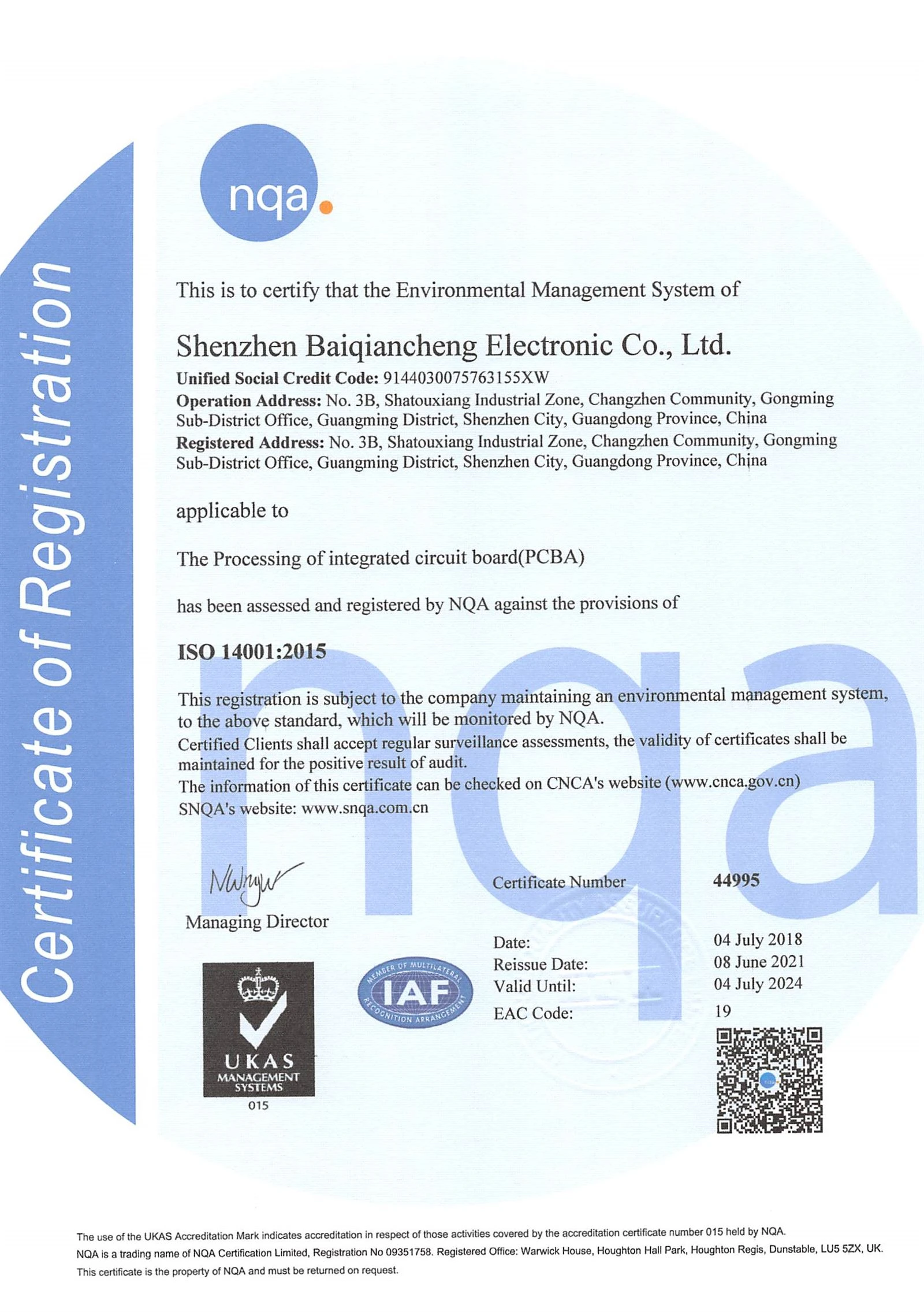
Certificates


Hot Tags: KVM switch PCBA, China, manufacturers, factory, customized, pcb through-hole technology, Solar Garden Light Pcb Board, PCBA Supplier For Medical Equipment, WIFI Controller Pcb Assembly Design Development, electronic medical products pcb assembly, energy storage BMS


