


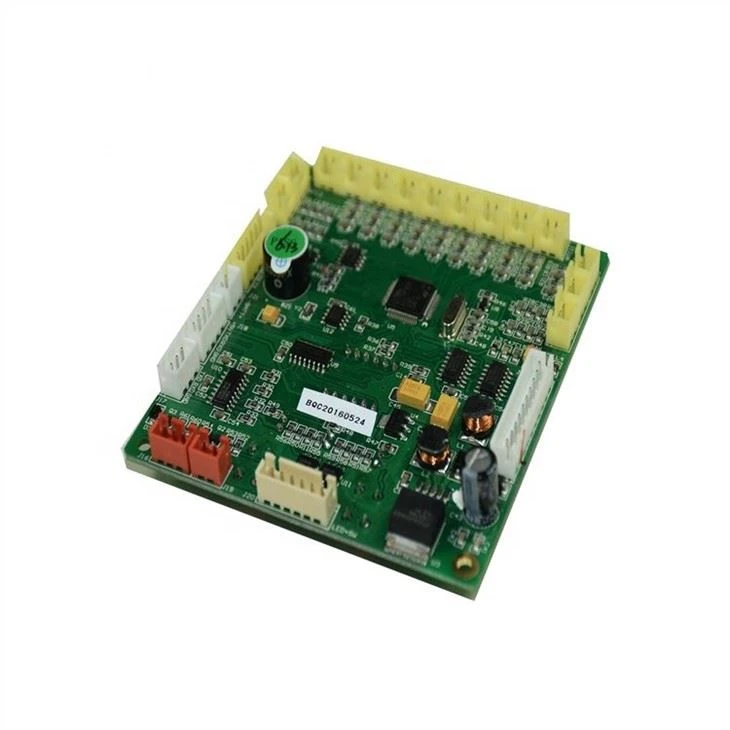
Products Description
The Fiber Transceiver PCBA is engineered as the high‑speed optical interface for modern communication networks. It integrates a laser driver and post‑amplifier for converting between high‑speed electrical signals and optical pulses across multimode or single‑mode fiber. The board features a transimpedance amplifier (TIA) with automatic gain control to maintain consistent receiver sensitivity over varying input optical power. Digital diagnostic monitoring (DDM) circuits provide real‑time reporting of temperature, supply voltage, laser bias current, and received optical power. The multi‑layer PCB design meticulously isolates sensitive analog photocurrent paths from high‑speed differential signal lines, ensuring low bit error rates at multi‑gigabit data rates. A precision current source drives the laser diode while an active back‑powering protection circuit prevents damage during hot insertion. Compact and thermally efficient, this PCBA fits standard SFP, SFP+, or QSFP form factors, making it suitable for datacom, telecom, and enterprise networking equipment requiring reliable optical‑electrical conversion.
PCBA Display


Production and Quality
Our manufacturing process for high‑speed optical interface boards follows strict quality protocols to ensure low bit error rates across temperature extremes. Each board undergoes In‑Circuit Test (ICT) and a Functional Test (FCT) using a calibrated optical loopback. The FCT validates laser driver modulation, transimpedance amplifier gain, digital diagnostic monitoring (DDM) accuracy, and alarm/warning thresholds. All optical parameters – transmit power, extinction ratio, receiver sensitivity – are measured and recorded per board.
We utilize advanced SMT lines with 3D SPI, Automated Optical Inspection (AOI), and X‑ray for fine‑pitch optoelectronic components. A selective conformal coating robot protects the board while keeping optical windows and gold fingers clean. Each unit passes thermal cycling from -40°C to +85°C while continuously streaming live traffic, followed by a final parametric retest.
Our supply chain includes long‑term agreements with laser diode, TIA, and driver IC suppliers. Standard lead time is 5‑6 weeks for volume orders. With high‑precision placement lines and dedicated optical test racks, we maintain scalable capacity to meet data center deployment schedules while ensuring industry‑leading quality and on‑time delivery.
Production Process
The assembly of high‑speed optical transceiver boards requires exceptional cleanliness and process control. Solder paste printing uses Type 4 or Type 5 powder with stencil designed for fine‑pitch optoelectronic ICs. Reflow is performed with a multizone oven under nitrogen atmosphere to prevent oxidation of gold‑plated pads and exposed copper. X‑ray inspection is mandatory for BGAs and laser diode packages, checking for voids and alignment. After reflow, a selective coating robot applies a thin, transparent conformal coating, with mask tooling protecting the optical receptacle and edge‑card connector. All assembly steps occur in an ESD‑safe, class 100,000 cleanroom to avoid particle contamination on optical surfaces. Panel depaneling uses a laser depanelizer for stress‑free singulation of the narrow, elongated board shape. Final assembly includes attachment of the optical receptacle and gold‑plated edge connector, followed by manual visual inspection under magnification. Each board is then inserted into a standard cage and tested in a powered burn‑in rack while streaming live traffic before final vacuum packing with desiccant for moisture‑sensitive devices.
Q&A
Q: What is the single most challenging aspect of manufacturing a fiber transceiver board compared to a standard digital PCBA?
A: The challenge is contamination control on optical surfaces. A speck of dust on the fiber coupling interface or a fingerprint on the laser diode window can cause 0.5 dB to 1 dB of optical loss, failing the link budget. Our assembly of a Fiber Transceiver PCBA occurs in a class 100,000 cleanroom. Operators wear cleanroom suits, and all handling uses vacuum pens, not fingers. After reflow, a special compressed air ionizer cleans every board before optical receptacle attachment. No such controls exist for standard digital boards.
Q: How do you verify that the conformal coating does not degrade optical performance?
Answer: We use a selective coating robot with precise mask tooling that completely blocks the optical receptacle and photodiode windows. Every shift, we perform a validation run: a coated board is compared to an uncoated control board. We measure transmit power and receiver sensitivity on both. The difference must be less than 0.1 dB. If it exceeds that, the mask is inspected and the coating process parameters are adjusted. This ensures coating never interferes with the optical path while still protecting the rest of the circuitry.
Q: Your datasheet mentions digital diagnostic monitoring (DDM). How do you test this feature efficiently on every board?
A: We built a custom test script that runs during the final optical FCT. A microcontroller on the test board emulates the host and reads back all DDM parameters – temperature, voltage, bias current, TX power, RX power. We then inject controlled optical power levels using an attenuator and verify that the reported values match the calibrated optical power meter within specification. This is fully automated; the board either passes all DDM parameters automatically or the operator receives a failing report. No manual reading of registers is needed, keeping throughput high.
Certificates


Hot Tags: Fiber Transceiver PCBA, China, manufacturers, factory, customized, PCBA control panel of air heater, control panel of air heater and electric heater, EMS PCBA Assembly For 16 Years, PCBA control panel of electric heater, Custom made PCBA


