


Products Description
The Pacemaker PCBA is an implant-grade control platform engineered for cardiac rhythm management devices. Built around a dual-die architecture pairing a 32-bit ultralow-power microcontroller with a dedicated analog therapy engine, it delivers real-time sensing, pacing, and defibrillation control within a 2.5 cm² footprint. The sensing front-end resolves intracardiac electrogram signals down to 10 µV while rejecting polarization artifacts, and the pacing output stage supports unipolar and bipolar configurations with programmable pulse amplitudes from 0.5 V to 7.5 V and pulse widths from 0.1 ms to 2 ms. The Pacemaker PCBA incorporates a high-voltage defibrillation switch matrix rated for 800 V, enabling biphasic waveform delivery with tilt control and charge-balancing verification. Telemetry uses a 402–405 MHz MICS band transceiver with AES-128 encryption, supporting firmware upgrades and diagnostic data retrieval at 2 meters. A dual-channel reed switch and Hall sensor provide magnetic programming detection, while the onboard battery manager tracks lithium-iodine cell impedance and predicts remaining longevity within ±5%. Therapy safety is enforced by independent watchdog circuits, redundant charge-delivery counters, and a hardware-based rate limiter that prevents pacing above 200 bpm. All stimulation paths undergo capacitive coupling to block DC leakage, and the board includes self-test routines executed every 24 hours to confirm output integrity and sensing threshold stability. The design meets ISO 14708-2 and IEC 60601-1 requirements, with the bare board and components qualified for long-term implantation.
Products Display


Products Advantages
The Pacemaker PCBA delivers reliability and longevity advantages that directly support patient safety and device service life. Its dual-die architecture isolates therapy delivery from communication and diagnostics, so a telemetry fault cannot propagate to the pacing output stage. The sensing front-end resolves 10 µV intracardiac signals while rejecting polarization artifacts, maintaining accurate arrhythmia detection even during lead maturation. Independent watchdog circuits, redundant charge-delivery counters, and a hardware rate limiter capped at 200 bpm provide layered protection against runaway pacing. The onboard battery manager tracks lithium-iodine cell impedance and predicts remaining longevity within ±5%, helping clinicians plan replacement intervals with confidence.
The Pacemaker PCBA achieves a standby current of 4.8 µA and a pacing current of 12 µA at 60 bpm with 2.5 V amplitude, extending projected device life beyond 12 years in typical dual-chamber configurations. High-voltage biphasic defibrillation delivery with tilt control and charge balancing reduces myocardial damage compared with monotonic waveforms. The 402–405 MHz MICS transceiver with AES-128 encryption enables secure firmware upgrades and diagnostic retrieval at 2 meters, eliminating surgical intervention for parameter adjustments. Every stimulation path is capacitively coupled to block DC leakage, and self-test routines run every 24 hours to verify output integrity and sensing threshold stability. The 2.5 cm² footprint allows smaller device form factors, while full compliance with ISO 14708-2 and IEC 60601-1 streamlines regulatory submission. These combined attributes reduce follow-up burden, extend replacement cycles, and improve patient outcomes.
Manufacturing Process
The fabrication process is built around implant-grade cleanliness and long-term reliability. Production starts with a 4-layer ceramic substrate using 96% alumina for its hermetic properties and dimensional stability, co-fired with tungsten metallization and finished with gold plating for wire-bondable and solderable surfaces. Laser drilling creates via holes down to 75 µm, which are filled with tungsten paste and co-fired at 1,600°C to achieve hermetic sealing. Titanium-nitride thin-film resistors are deposited and laser-trimmed to ±0.1% tolerance for sensing and reference circuits.
Assembly takes place in an ISO Class 5 cleanroom with strict particle and ionic control. Bare dies are attached using gold-tin eutectic bonding at 300°C, achieving void rates below 2% verified by X-ray. Gold wire bonding interconnects the microcontroller, analog front-end, and high-voltage switch matrix, with pull-test sampling on every lot. Hermetic feedthroughs are brazed to the substrate for external lead connections. Components are then sealed under a dry nitrogen atmosphere with a ceramic lid using a gold-tin seal ring, producing a leak rate below 1×10⁻⁹ atm·cc/s as confirmed by helium fine-leak testing.
Each unit undergoes full electrical characterization including sensing threshold resolution, pacing output accuracy, and defibrillation switch isolation at 800 V. A 1,000-hour accelerated life test at 37°C and 90% RH validates parameter drift below 2%. Final inspection includes scanning acoustic microscopy for die-attach voids and visual verification under magnification. All process data is serialized and archived for the lifetime of the implant.
Q&A
Q1: What cleanroom and contamination-control standards apply to your implantable-grade production?**
A: Assembly occurs in an ISO Class 5 cleanroom with continuous particle monitoring and positive-pressure airflow. All operators wear full gowning including hoods, masks, and nitrile gloves changed every two hours. We perform ionic contamination testing per IPC-TM-650 on every lot, requiring residues below 0.1 µg NaCl equivalent per cm². A helium fine-leak test at 1×10⁻⁹ atm·cc/s confirms hermetic sealing after lid attachment, and each batch undergoes destructive physical analysis on samples to verify die-attach void rates below 2%.
Q2: How do you validate long-term reliability for a device expected to function over 10 years?**
A: We run 1,000-hour accelerated life testing at 37°C and 90% RH with continuous electrical monitoring, requiring parameter drift below 2%. Temperature cycling from -20°C to 85°C over 500 cycles validates solder and bond integrity. We also perform highly accelerated stress testing at 130°C and 85% RH for 96 hours on sample units. All test data feeds into reliability models that predict failure rates below 0.1% over a 12-year service life.
Q3: What documentation and traceability do you provide for regulatory submissions?**
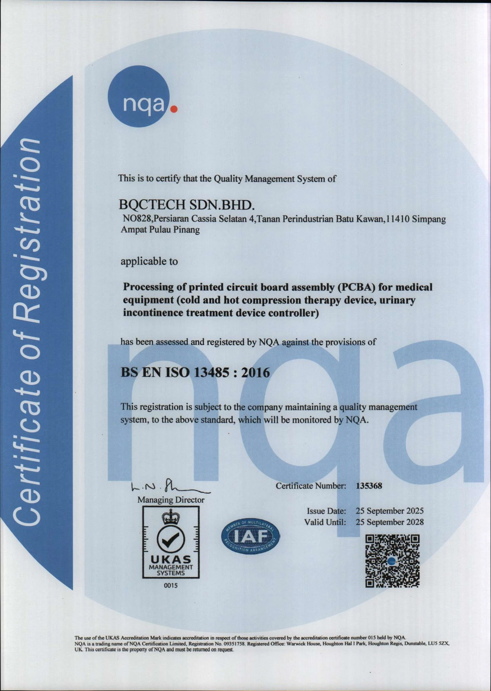
A: Every unit ships with a serialized certificate containing sensing resolution, pacing output accuracy across the full amplitude range, and high-voltage isolation test results. We provide a full production data package including wire-bond pull-test records, X-ray images of die attach, helium leak-test logs, and scanning acoustic microscopy reports. Our quality system is ISO 13485 certified, and documentation is formatted to align with FDA PMA and EU MDR requirements, streamlining your regulatory compilation.
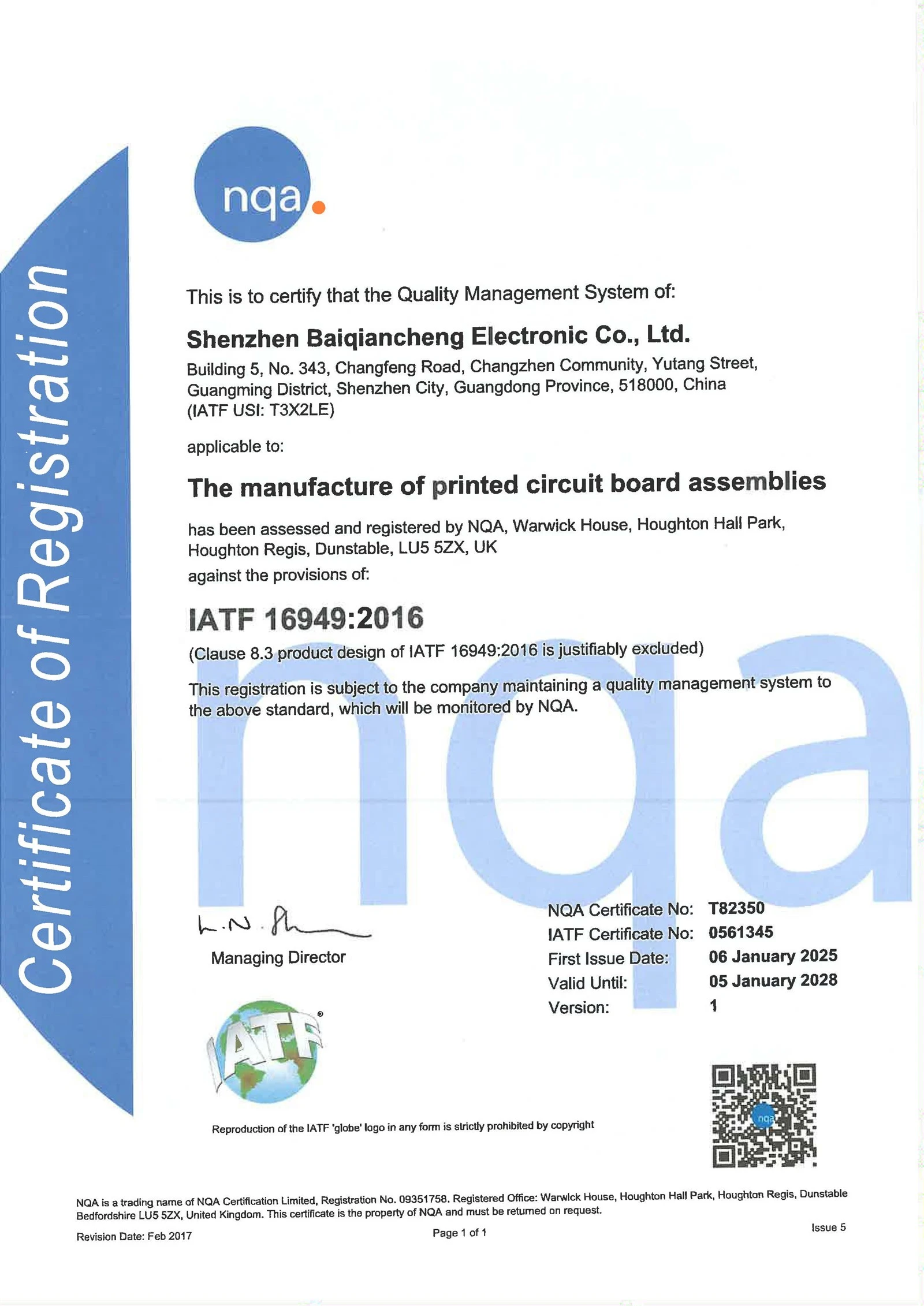
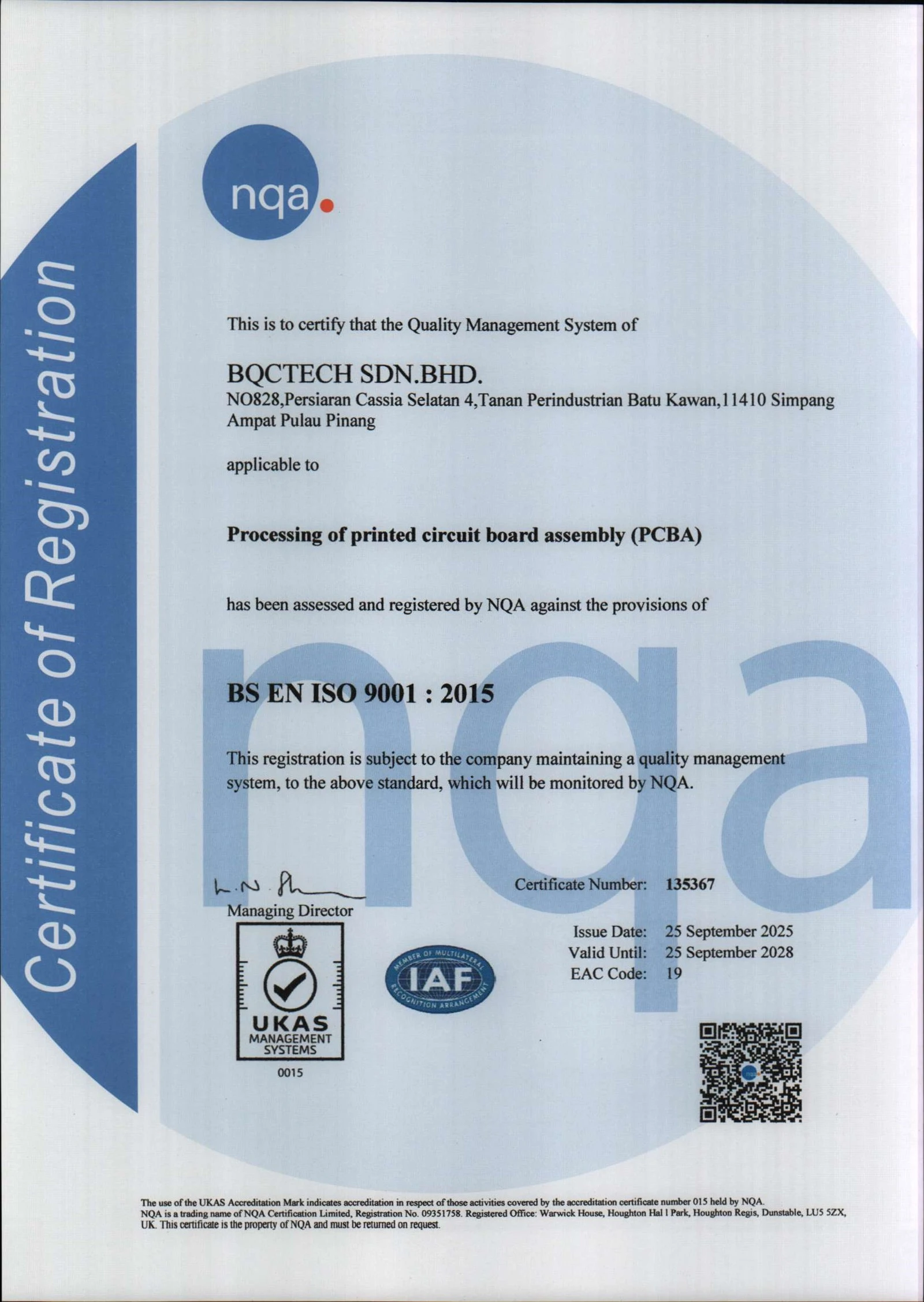
Certificates

Hot Tags: pacemaker pcba, China, manufacturers, factory, customized, medical PCBA, pcb assembly techniques, pcb installation, pcb plating, Printed Circuit Board Assembly, SMT


