


Products Description
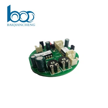
The Motion Controller PCBA is engineered as the high‑performance computational core for precise multi‑axis motion control in automation and robotics. It integrates a dedicated motion control processor or FPGA that executes complex interpolation algorithms, including linear, circular, and electronic gearing, with update rates up to 10kHz per axis. The board supports multiple encoder interfaces (incremental, absolute, and SSI) with differential line receivers for noise immunity, and provides analog ±10V or PWM outputs for servo and stepper drives. A high‑speed backplane interface enables synchronization across multiple boards for large‑scale systems. On‑board memory stores cam tables and motion profiles, allowing standalone operation without a host PC. The PCB uses controlled‑impedance traces for high‑speed encoder feedback, with separate power and ground planes to isolate sensitive analog command signals from digital switching noise. Designed for industrial environments, the PCBA includes isolated digital I/O for limit switches and home sensors, and conformal coating for protection against dust and moisture. It is suitable for CNC machines, packaging equipment, and robotic arms.
PCBA Display



Production Process
The assembly of multi‑axis motion control boards requires precise handling of high‑speed digital and sensitive analog sections. Solder paste printing uses Type 4 or Type 5 powder with SPI to ensure consistent volume on fine‑pitch pads of the motion processor, FPGA, and high‑speed encoder interface ICs. Reflow is performed with a multizone oven under nitrogen, using a profile that avoids thermal damage to sensitive analog command output stages while fully melting solder beneath large BGA packages. X‑ray inspection is mandatory for all BGAs and fine‑pitch connectors. After reflow, selective soldering attaches thru‑hole connectors (encoder terminals, servo command headers, power input) and any board‑to‑board backplane connectors. A robotic selective coating robot applies a thin conformal coating, with mask tooling protecting connector pins, test points, and analog output terminals. Board depanelization uses routing with entry/backup material to prevent mechanical stress that could affect precision components. Final assembly includes installation of heatsinks on the motion processor and any required EMI shielding cans over high‑speed digital sections. Each board then undergoes powered programming of the motion firmware and a quick functional check before packing in anti‑static bags with humidity indicator cards. All assembly is performed in ESD‑safe workstations with controlled humidity, and analog sections are handled with clean gloves to prevent contamination.
Production and Quality
Our manufacturing process for multi‑axis motion control boards follows rigorous quality protocols to ensure precise and reliable operation. Each board undergoes In‑Circuit Test (ICT) and a comprehensive Functional Test (FCT) using a motion simulation rack. The FCT validates encoder feedback processing, analog command output linearity (±10V), PWM pulse timing, interpolation accuracy, and multi‑axis synchronization. Limit switch and home sensor input response are verified for timing and debounce. Backplane communication integrity is tested with a reference host.
We utilize advanced SMT lines with 3D SPI, Automated Optical Inspection (AOI), and X‑ray for BGA and fine‑pitch connectors. A conformal coating is applied to protect against dust and moisture. Each board passes a 48‑hour burn‑in test at elevated temperature with continuous motion commands to screen early failures and verify long‑term stability.
Our supply chain includes long‑term agreements with motion processor, FPGA, and encoder interface IC suppliers. Standard lead time is 7‑8 weeks for volume orders. With high‑precision placement lines and dedicated motion test racks, we maintain scalable capacity to meet industrial automation production schedules while ensuring consistent quality and on‑time delivery.
Certificates


Q&A
Q: What is the most overlooked factor that causes position errors in multi‑axis motion systems?
A: The most overlooked factor is ground noise coupling between the encoder interface and the analog command output. A Motion Controller PCBA often has differential encoder receivers and ±10V servo command outputs on the same board. If the analog ground is not carefully isolated from the digital ground, switching noise from the encoder signals can modulate the command voltage, causing microscopic position jitter that accumulates over time. We solve this by using a separate analog ground plane with a single‑point star connection, and by placing common‑mode chokes on every encoder input pair. During FCT, we verify this by running the encoder at maximum frequency while measuring the analog output with a precision voltmeter; any ripple above 1mV triggers a rejection.
Q: How do you test interpolation accuracy without a mechanical stage on every production board?
Answer: We use a synthetic encoder simulator that generates quadrature signals with known phase relationships and jitter. The board is commanded to follow a circular interpolation path, and we monitor the analog output commands. The test system calculates the commanded position from the analog outputs and compares it to the ideal circle. The maximum radial error must be less than one encoder count. This test is fully automated and runs in under 10 seconds per board, avoiding the cost and complexity of a real motion stage.
Q: What special measures ensure that multi‑axis synchronization remains stable over long production runs?
Answer: We implement hardware‑based synchronization rather than relying on software interrupts. A dedicated sync bus on the backplane connector distributes a common clock and trigger signal to all axes. The FPGA on each board locks its internal timer to this sync signal with a phase‑locked loop. During burn‑in, we run all axes in a coordinated pattern and measure the skew between axes using a logic analyzer. The skew must remain within ±10ns over the entire test. Any board exceeding this limit indicates a PLL or layout issue and is rejected. This test is performed on every board, not just samples.
Hot Tags: motion controller pcba, China, manufacturers, factory, customized, pcb for medical devices, pcb terminals, pcba air conditioning system, pcba ventilation system, precision pcb fabrication, smt approach


