


Products Description
The PCBA for Photocopier is engineered as the central command and power distribution center for high‑volume document reproduction systems. It integrates a multi‑core processor that manages image scanning, digital processing, electrostatic printing, and paper handling in real time. High‑voltage power generation circuits – for charge corona, transfer roller, and developer bias – are precisely controlled via closed‑loop feedback from current monitors. Stepper motor drivers with advanced micro‑stepping handle paper feed, drum rotation, and scanner carriage movement. The board also interfaces with the fuser heater controller, document feeder sensors, and user‑interface panel. A multi‑layer PCB design meticulously separates high‑voltage sections (up to several kilovolts) from low‑voltage digital logic and sensitive analog image signal paths. Comprehensive safety features include interlock detection, over‑current protection, and discharge resistors. Designed for continuous operation in office and production environments, this PCBA maintains reliable performance across millions of copy cycles.
PCBA Display


Production & Quality
Our manufacturing process for high‑voltage document system boards follows rigorous safety and reliability protocols. Each board undergoes In‑Circuit Test (ICT) followed by a comprehensive Functional Test (FCT) using a specialized fixture that simulates a photocopier chassis. The FCT validates high‑voltage generation accuracy (charge corona, transfer, developer bias), stepper motor timing, fuser heater control with thermistor feedback, and interlock safety circuits. High‑voltage outputs are measured with a calibrated HV probe, and leakage current is verified to be below specification.
We utilize advanced SMT lines with 3D SPI, Automated Optical Inspection (AOI), and X‑ray for BGA and power components. Creepage and clearance distances are maintained by selective conformal coating robot with mask tooling covering only low‑voltage sections. Each board passes a 48‑hour powered burn‑in with simulated copy cycles to screen early failures. Sample boards from each batch are destructively tested for HV withstand and arc resistance.
Our supply chain includes long‑term agreements with HV generator and stepper driver suppliers. Standard lead time is 6‑7 weeks for volume orders. With high‑precision placement lines and dedicated HV test racks, we maintain scalable capacity to meet office equipment production schedules while ensuring consistent quality and on‑time delivery.
Production Process
The assembly of high‑voltage photocopier boards demands strict process controls to prevent arcing and ensure operator safety. Solder paste printing uses Type 4 powder with precise SPI verification, especially for large power packages and high‑voltage multiplier modules. Reflow is performed with a multizone oven under nitrogen, using a slow ramp‑soak profile to avoid thermal shock to ceramic HV capacitors. X‑ray inspection is mandatory for BGA devices and any voids in high‑current power inductors. Selective soldering attaches thru‑hole components such as high‑voltage connectors and transformer pins. After soldering, a robotic selective coating robot applies conformal coating exclusively to low‑voltage sections, leaving high‑voltage traces and components bare to avoid unintended surface leakage. Mask tooling precisely covers HV zones. Board depanelization uses routing with entry/backup material to prevent burrs on high‑voltage isolation slots. Final assembly includes installation of insulation barriers, heatsinks with insulated shoulder washers, and high‑voltage wiring harnesses. Each board is then cleaned with a specialized flux remover and visually inspected under UV light to confirm coating coverage before proceeding to high‑voltage functional test.
Q&A
Q: What is the most dangerous latent defect in a photocopier high‑voltage board, and how do you screen for it?
A: The most dangerous defect is partial discharge (corona) that doesn't cause immediate failure but degrades insulation over time. A PCBA for Photocopier operates at several kilovolts. A small bubble in conformal coating or a sharp solder residue can create a corona that carbonizes the PCB material. After months, it may arc, damaging the machine and creating a fire risk. We screen for this using a partial discharge test with a specialized AC hipot set. A passing board shows no discharge activity above 10pC at 1.5x nominal voltage. This is mandatory on every board, not just samples.
Q: How do you verify the interlock safety circuit will actually shut down high voltage when the door opens?
Answer: We perform a forced fault injection during FCT. A relay in the test fixture simulates the door interlock switches. While the high‑voltage outputs are active, we open the simulated door contacts. The PCBA must drop the high voltage to below 50V within 100ms and latch off. We also inject a stuck‑closed failure (bypassing the interlock) to verify that a secondary thermal fuse or crowbar circuit activates. This dual‑level test ensures safety even if one component fails.
Q: Your board drives multiple stepper motors for paper path and optics. How do you prevent motor stalls from damaging the gears?
Answer: We implement hardware stall detection independent of firmware. Each motor driver includes a current sense circuit that trips a comparator when current exceeds a preset threshold for more than a few milliseconds. This comparator forces the driver enable low, bypassing the microcontroller. The firmware can read the stall flag later. This prevents the gears from grinding and stripping during a paper jam. We verify this stall detection on every board by mechanically locking the motor shaft with a fixture pin and commanding motion; the board must shut down within 5ms. The test fixture records a pass/fail per motor.
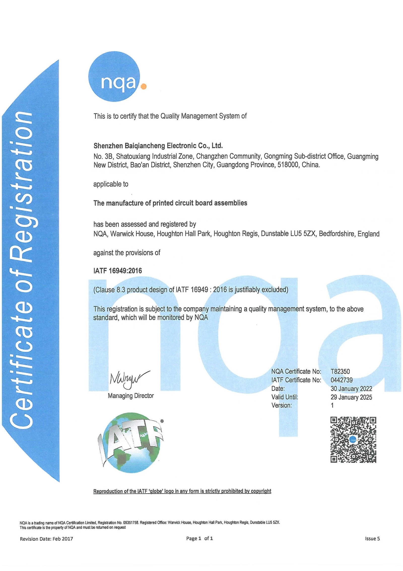
Certificates


Hot Tags: PCBA for Photocopier, China, manufacturers, factory, customized, pcb assembly with custom packaging, PCB Assembly Industrial Box Controller, double-sided pcb assembly, pcb assembly with inspection and testing, pcb assembly with marking and labeling, pcb assembly with nfc modules


