


Products Description
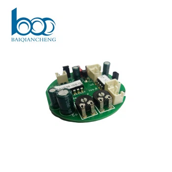
The PCBA for PLC is engineered as the high‑reliability control core for industrial automation and power line communication systems. It integrates a powerful microcontroller or FPGA with a robust analog front‑end for signal conditioning, filtering, and amplification. The board features a dedicated FSK or OFDM modem that modulates data onto AC/DC power lines, enabling communication over existing electrical wiring without dedicated data cables. A precision zero‑crossing detector and adaptive gain control ensure reliable data capture in noisy environments with fluctuating line impedance. On‑board isolated power supplies and optocoupler‑based I/O interfaces protect the digital section from high‑voltage transients. The PCB design employs separate analog and digital ground planes with careful component placement to minimize crosstalk between the power line coupler and the processing core. Designed for DIN‑rail or panel mounting, the PCBA supports industrial temperature ranges, wide input voltage, and robust surge protection. It is suitable for smart metering, lighting control, energy management, and industrial sensor networks, delivering stable data communication even in harsh factory conditions.
PCBA Display


Production Process
The assembly of power line communication boards requires careful segregation of high‑voltage coupler sections from sensitive digital processing. Solder paste printing uses Type 4 powder with SPI to ensure consistent volume on fine‑pitch pads of the modem IC, MCU/FPGA, and analog front‑end components. Reflow is performed with a multizone oven under nitrogen, optimizing wetting while preventing voiding under large packages. X‑ray inspection is mandatory for BGA devices and for verifying via‑in‑pad connections under power components. After reflow, selective soldering attaches thru‑hole connectors (power input, I/O terminals) and high‑voltage coupler transformers. A robotic selective coating robot applies a thick conformal coating, with mask tooling protecting connector pins, test points, and high‑voltage isolation slots. Board depanelization uses routing with entry/backup material to prevent burrs. Final assembly includes installation of heatsinks on the modem IC and power supply components, along with any required isolation barriers. Each board then undergoes powered programming of the modem firmware and base parameters before final visual inspection and packing in anti‑static bags. All assembly takes place in ESD‑safe workstations with controlled humidity to protect sensitive mixed‑signal components.
Production & Quality
Our manufacturing process for power line communication control boards follows rigorous quality protocols to ensure reliable data transmission over noisy power lines. Each board undergoes In‑Circuit Test (ICT) and a comprehensive Functional Test (FCT) using a live power line simulator. The FCT validates modem modulation/demodulation, zero‑crossing detection, adaptive gain control, and I/O interface response under varied line impedance and noise injection. Isolated power supplies and surge protection circuits are verified with high‑voltage tests.
We utilize advanced SMT lines with 3D SPI, Automated Optical Inspection (AOI), and X‑ray for BGA and power components. A thick conformal coating is applied for protection against dust and moisture. Each board passes a 48‑hour burn‑in test with continuous communication traffic over a simulated noisy power line to screen early failures.
Our supply chain includes long‑term agreements with modem IC, MCU, and analog front‑end suppliers. Standard lead time is 6‑7 weeks for volume orders. With high‑precision placement lines and dedicated PLC test racks, we maintain scalable capacity to meet industrial automation production schedules while ensuring consistent quality and on‑time delivery.
Q&A
Q: What is the most challenging aspect of PLC design that is rarely discussed in marketing literature?
A: The most challenging aspect is adaptive impedance matching. A PCBA for PLC must communicate over power lines whose impedance varies wildly (from 2Ω to 100Ω) depending on connected appliances and time of day. A fixed coupling network will fail in the field. Our design uses a programmable analog front‑end with switchable capacitors and transformers, controlled by firmware that runs a line‑sounding routine during initialization. This routine measures line impedance and selects the optimal coupling setting. During FCT, we test this adaptation by changing the simulator's impedance in steps and verifying that the board re‑optimizes its coupling.
Q: How do you test for real‑world noise immunity without a complex power line simulator?
Answer: We built a custom noise‑injection fixture that can superimpose dimmer buzz, motor commutation spikes, and switch‑mode supply noise onto the clean 230V/110V waveform. During FCT, the board is commanded to transmit a known test pattern while we inject each noise type at increasing levels. The board must maintain a BER better than 10⁻⁵. The pass/fail threshold is calibrated against a golden board. This is more realistic than simple SNR tests and can be performed on every unit without expensive network analyzers.
Q: What specific measures do you take to ensure long‑term reliability of the high‑voltage coupler section?
Answer: We use triple‑coated transformer insulation and maintain a minimum 8mm creepage distance between primary and secondary. All high‑voltage capacitors are selected with X1/X2 safety ratings. The assembly is subjected to a 2kV dielectric withstand test for 60 seconds during production. But we go further: a statistical sample from each batch is subjected to a damp‑heat test at 85°C/95% RH for 168 hours while powered, followed by a full parametric test. This screens for gradual insulation degradation that would otherwise appear only after years in the field.
Certificates


Hot Tags: PCBA for PLC, China, manufacturers, factory, customized, cost-effective pcb assembly, pcb assembly with iso certification, Air Conditioner Controller Board Pcb Assembly Pcba, pcb assembly with antennas, pcb assembly with digital circuits, pcb assembly with gps modules


