In the dynamic world of electronics manufacturing, PCB (Printed Circuit Board) and PCBA (Printed Circuit Board Assembly) play a pivotal role. As a trusted PCB PCBA Assembly supplier, we understand the significance of rigorous inspection during the assembly process. This blog will delve into the essential inspection items that ensure the quality and reliability of our PCB PCBA products.
Visual Inspection
Visual inspection is the first line of defense in the PCB PCBA assembly process. It involves a thorough examination of the board and its components with the naked eye or with the aid of magnifying tools. This inspection is carried out at multiple stages, from the arrival of raw materials to the final assembled product.
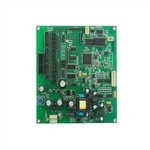
Component Placement
One of the primary aspects of visual inspection is checking the component placement. Components should be accurately positioned on the PCB according to the design specifications. Any misalignment, even by a fraction of a millimeter, can lead to electrical connectivity issues or mechanical problems. For example, if a surface - mount device (SMD) is placed too close to another component, it may cause short circuits. We ensure that all components are placed precisely, with their orientation and polarity correct. This is especially crucial for components like diodes and electrolytic capacitors, which can malfunction if installed backwards.
Soldering Quality
Soldering is a critical process in PCBA assembly, and visual inspection helps identify soldering defects. A good solder joint should have a smooth, shiny appearance and a proper fillet shape. Common soldering defects that can be detected visually include solder bridges, which occur when solder connects two adjacent pads that should be electrically isolated. This can cause short circuits and disrupt the normal operation of the circuit. Another defect is insufficient solder, where there is not enough solder to form a reliable electrical and mechanical connection. This can lead to intermittent connections and premature failure of the component. By carefully inspecting each solder joint, we can catch these issues early and rectify them.
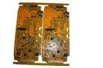
Board Condition
The condition of the PCB itself is also inspected during the visual inspection process. We look for any physical damage to the board, such as scratches, cracks, or delamination. These defects can weaken the structural integrity of the board and may affect the performance of the assembled circuit. Additionally, we check for any signs of contamination on the board, such as dust, debris, or flux residues. Contamination can cause corrosion and electrical leakage, which can degrade the long - term reliability of the PCBA.
Electrical Testing
After the visual inspection, electrical testing is conducted to ensure that the PCB PCBA functions as intended. This type of testing verifies the electrical connectivity and performance of the circuit.
Continuity Testing
Continuity testing is performed to check if there is a complete electrical path between different points on the PCB. Using a multimeter or a specialized continuity tester, we can measure the resistance between two points. A low resistance value indicates a good electrical connection, while a high resistance or an open circuit suggests a connectivity issue, such as a broken trace or a faulty solder joint. This test is crucial for identifying shorts and opens in the circuit, which can prevent the proper flow of current.
Functional Testing
Functional testing involves applying power to the assembled PCBA and verifying that it performs all the specified functions correctly. We use test fixtures and automated test equipment to simulate the normal operating conditions of the product. For example, if the PCBA is designed to control a motor, we will test if it can start, stop, and vary the speed of the motor according to the input signals. Any deviation from the expected functionality indicates a problem with the assembly, which could be due to a faulty component, improper soldering, or design flaws.


In - Circuit Testing (ICT)
In - Circuit Testing is a more comprehensive electrical testing method that checks the individual components and their connections on the PCB. It uses a bed - of - nails tester, which has a set of spring - loaded pins that make contact with the test points on the PCB. ICT can measure the electrical parameters of components, such as resistance, capacitance, and inductance, and compare them with the expected values. This test can detect component failures, incorrect component values, and soldering issues at the component level.
RoHS Compliance Inspection
As an environmentally - conscious PCB PCBA Assembly supplier, we also conduct inspections to ensure RoHS (Restriction of Hazardous Substances) compliance. RoHS is a European Union directive that restricts the use of certain hazardous substances in electrical and electronic equipment, including lead, mercury, cadmium, hexavalent chromium, polybrominated biphenyls (PBBs), and polybrominated diphenyl ethers (PBDEs).
We source our components from suppliers who are certified to be RoHS - compliant. During the inspection process, we check the documentation provided by the suppliers to verify the compliance of the components. Additionally, we may use analytical techniques, such as X - ray fluorescence spectroscopy, to detect the presence of restricted substances in the PCB and components. Ensuring RoHS compliance not only helps us meet the regulatory requirements but also demonstrates our commitment to environmental protection.
X - ray Inspection
X - ray inspection is a non - destructive testing method that can reveal hidden defects inside the PCB and components. It is particularly useful for detecting solder joint defects in components with a high pin count or in components that are difficult to access visually, such as ball grid array (BGA) packages.
An X - ray machine is used to generate an image of the internal structure of the PCB and components. By analyzing the X - ray image, we can detect voids in the solder joints, which can reduce the reliability of the connection. We can also check if the solder has properly wetted the pads and pins, ensuring a good electrical and mechanical connection. X - ray inspection provides a more in - depth view of the assembly quality and helps us identify potential issues that may not be visible through visual inspection alone.
Burn - In Testing
Burn - in testing is a long - term testing method that aims to identify early - life failures in the PCB PCBA. During this test, the assembled PCBA is powered on and operated at an elevated temperature and voltage for an extended period, typically several hours to several days.
The high - stress conditions during burn - in testing accelerate the failure mechanisms, allowing us to detect weak components or soldering joints that may fail prematurely in normal operation. Components that are prone to failure, such as capacitors and integrated circuits, are more likely to show signs of degradation during burn - in testing. By removing the defective units at this stage, we can ensure that only high - quality products are delivered to our customers.
In conclusion, as a PCB PCBA Assembly supplier, we are committed to providing our customers with high - quality products. Through a comprehensive inspection process that includes visual inspection, electrical testing, RoHS compliance inspection, X - ray inspection, and burn - in testing, we can ensure the reliability and performance of our PCB PCBA products. If you are in need of Building Automation Robotics PCBA Assembly, Automatic Equipment Controller PCB Assembly, or Electronic Product Development & Design And PCBA Assembly Services, we invite you to contact us for procurement discussions. We are ready to work with you to meet your specific requirements and provide you with the best solutions.
References
- IPC Standards for Printed Circuit Board Assembly
- Electronic Engineering Textbooks on PCB and PCBA Manufacturing
- RoHS Directive Documentation